
I. Product Overview
-
Application
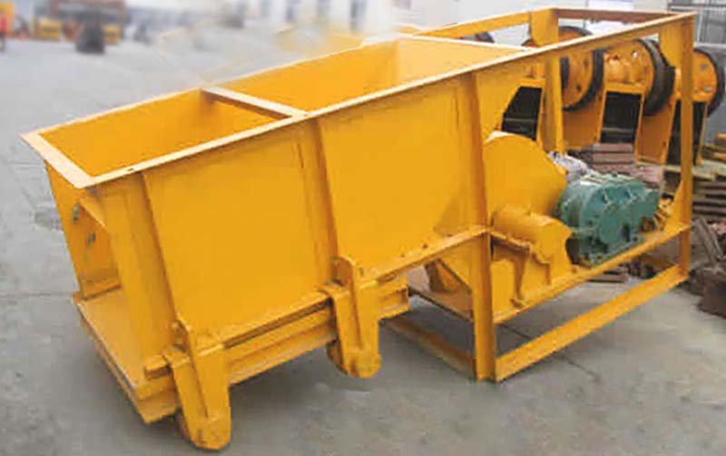
The trough feeder (also known as a chute feeder) is a reciprocating feeding device suitable for industries such as mining, metallurgy, chemicals, coal, and building materials. It uniformly conveys lumpy or granular materials (particle size ≤350 mm) from storage silos to receiving equipment (such as crushers or conveyors). The conveyance of powdery materials is strictly prohibited.
-
Structural Components
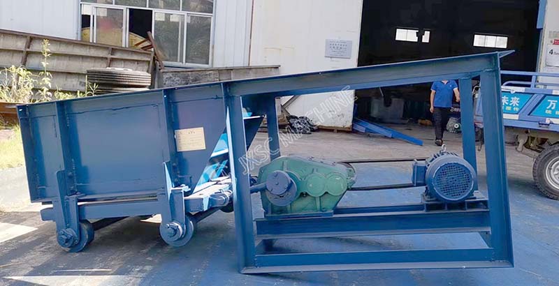
It primarily consists of a motor, reducer, coupling, eccentric mechanism, trough body, feed plate (perforated plate), rollers, adjustment gate, safety guard, and other components.
-
WorkingPrinciple
The motor drives the gear reducer, which, through an eccentric mechanism, causes the feed plate to move back and forth in a linear motion on the rollers (20–60 strokes per minute, with a stroke length of 20–200 mm). This is combined with an adjustable gate to control the material bed thickness, ensuring uniform and continuous feeding.
-
Technical Specifications (Common Models)
| Model | Max feeding(mm) | Capacity(t/h) | Motor power |
| CG600*500 | 200 | 10-50 | 4 |
| CG980*1240 | 350 | 30-90 | 7.5 |
II. Installation and Commissioning
-
Installation
- – Foundation: Install on a level concrete foundation and secure with anchor bolts; the unit may be place directly on the ground or suspended from the discharge spout of a silo.
- – Leveling: Ensure the trough is level, with the feed plate making even contact with the rollers and no jamming.
- – Drive System: Coaxiality of the motor, reducer, and coupling must be ≤0.5 mm; the belt tension must be appropriate, and all protective covers must be complete and secure.
- – Electrical System: Grounding must be reliable, insulation resistance must be ≥1 MΩ, and there must be no exposed wiring.
-
No-Load Test Run
- Inspection: Check that all bolts are tightened, lubrication is adequate, and there is no debris.
- Test Run: Start the motor, observe the direction of rotation (consistent with the markings), and ensure there are no abnormal noises or jamming.
- Operation: Run continuously under no-load conditions for 30 minutes; bearing temperature rise ≤40°C; no oil leakage or abnormal noises from the reducer; current remains stable.
-
Load Test
- – Start with a small feed rate and gradually increase to the rated load; run for 1–2 hours.
- – Check for uniform feeding and no material blockages; ensure no parts are loose, no abnormal noises, and no oil leaks.
- – Verify that the regulating gate and eccentric wheel adjust smoothly, and that the adjustable feeding range meets specifications.
III. Operating Procedures
-
Pre-startup Inspection (Mandatory)
- Lubrication: Ensure the oil level in the gearbox reaches the mark, and that all grease nipples are adequately lubricate.
- Fasteners: Check that all bolts and pins are tight; ensure the feed plate and rollers show no signs of wear or misalignment.
- Electrical: Ensure the motor is properly grounded; switches and buttons are in good condition; and the ammeter is at zero.
- Safety: Ensure all protective guards are complete and secure; keep the area around the equipment clear of personnel and debris.
- Hopper: Ensure the material particle size meets requirements; no chunks or foreign objects are present.
-
Startup Procedure
- Confirm that all checks are complete and correct, then issue the startup signal.
- Turn on the power switch to start the motor. Run the machine under no-load conditions for 1–2 minutes. Once no abnormal noises, slowly open the regulating gate and gradually increase the feed rate to normal operating conditions.
- During operation: Observe that feeding is uniform and there is no material blockage; ensure motor current and bearing temperature are normal (temperature rise ≤40°C); check for no abnormal noises, vibrations, or oil leaks.
-
Shutdown Procedures
- Normal Shutdown: First, close the hopper gate. After the material in the trough has been completely discharged, press the stop button and turn off the power switch.
- Emergency Shutdown: In the event of material blockage, unusual noises, smoke, or electrical leakage, immediately pull the power switch to shut down the machine. Troubleshoot and resolve the issue after the system shuts down.
-
Operational Adjustments
- – Feed Rate: Adjust the gate opening (to control material layer thickness) or the eccentric wheel’s eccentricity (to adjust the stroke; eccentricity = stroke/2; for sticky materials, eccentricity ≥ 30 mm).
- – Blockage Prevention: Avoid using oversized or wet, sticky materials; in case of a blockage, stop the machine first and clear it manually; never attempt to dislodge material while the machine is running.
IV. Maintenance
-
Daily Maintenance (Every Shift)
- – Cleaning: Remove debris and dust from the trough and machine body.
- – Inspection: Check that bolts are tight, feed plates/rollers show no wear, there are no lubricant leaks, and motor/bearing temperatures are normal.
- – Logging: Record operating current, temperature, unusual noises, and other conditions.
-
Periodic Maintenance
- – Weekly: Check belt tension and the secure fit of protective covers; grease all grease fittings; tighten loose bolts.
- – Monthly: Check the oil level and quality in the gearbox; replace if degraded; inspect the wear on the eccentric wheel and connecting rod.
- – Quarterly: Inspect the wear on the feed plate and rollers; replace if severe; align the motor and gearbox for coaxiality.
- – Annually: Disassemble the entire machine for inspection and replace worn parts; perform maintenance on the motor and gearbox, and replace lubricating oil/grease.
-
Lubrication Specifications
- – Gearbox: Industrial gear oil (N100); maintain oil level at the mark; check monthly and replace quarterly.
- – Bearings/Pins: Calcium-based grease (ZG-2); grease once per shift.
- – Before lubrication: Clean the grease nipple/filling port to prevent dust from entering.
V. Safety Precautions
- Operators must be properly trained and familiar with the equipment’s structure, operating principles, and procedures; unlicensed personnel are not permitted to operate the equipment.
- During operation: Do not reach into the hopper or touch moving parts; do not stand on the equipment or lean against the machine body; do not step over the equipment.
- Maintenance/Cleaning: The machine must be shut down, disconnect the power , and a warning sign posted; proceed only after the equipment has come to a complete stop.
- Electrical Safety: Ensure reliable grounding and that wiring is undamaged; in damp environments, conduct thorough insulation checks to prevent electric shock.
- Material Jam Handling: Immediately shut down the machine and clear the jam manually; under no circumstances should hands or tools be used to dislodge material while the machine is running.
- Personal Protective Equipment: Wear a safety helmet, work clothes, a dust mask, and safety shoes while working.
We offer customization for additional models to meet the diverse requirements of our customers. The price of the mining equipment will be determined by the manufacturer’s type, machine model, manufacturing process capacity, etc. You are welcome to consult JXSC‘s professional engineers to get a quotation based on your requirements. We can design a sand-making and crushing production line flow chart for you.
